
| The plastic top-left body
cover comes off easily. Underneath I saw the need to remove this
circuit board. The lower left image shows the solder removed and
the right hand image shows the very tidy job I made of re-soldering it
afterwards. Later I decided I didn't actually have to remove this board and could work around it, with care. |
Check out the insanity and joy of one person's F4 purchase here. |
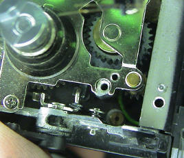
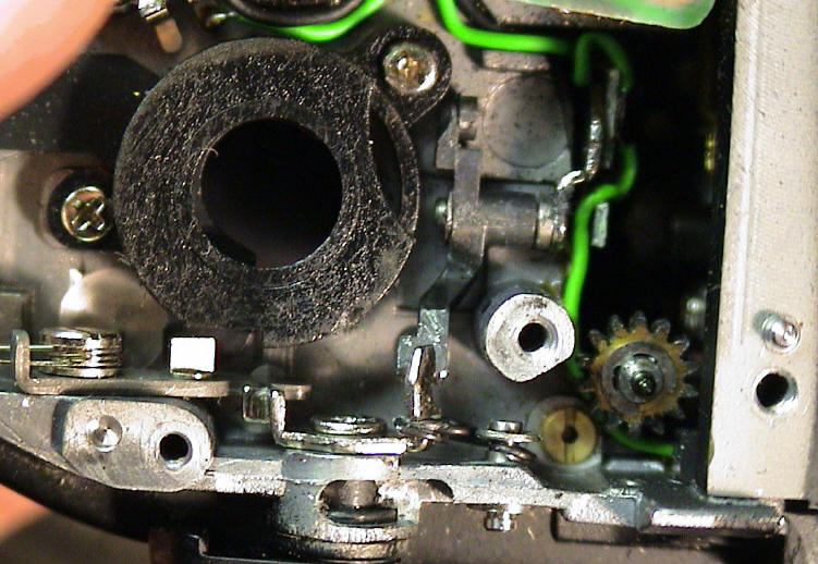
| This little lever here on
the left normally engages the rewind gearing. The interlock for
this lever is inside the cover-plate. The lever was worn out where the
lock grabs it thus allowing it to shift into action if moved while the
camera was being used. The gearing would then jam up. Simple? Nope. After replacing the lever with a new item and returning the camera, it jammed up again after a dozen rolls of film had gone through. The owner insisted he hadn't moved that lever by mistake. I accepted that of course and proceeded with a careful disassembly whilst it was still jammed up. |
![]()
![]()
![]()
![]()
![]()
![]()
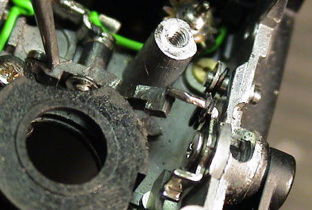
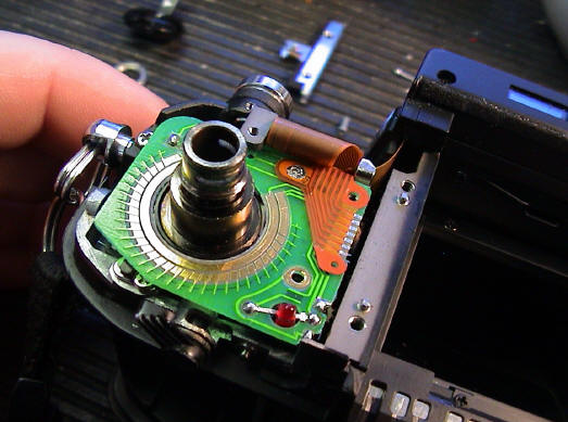
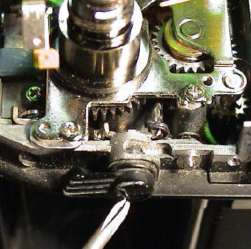
| The lever in
question, on the right here, is now in operational position (up).
It presses down on another lever (red arrow) which in turn pushes
upwards via a small bearing (orange arrow) on the underside of a cog.
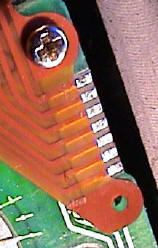
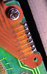
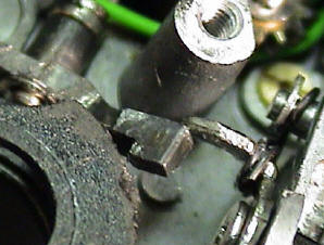
This cog then engages the rewind motor. Now, given suitable pressure, these two levers were able to slip past each other as indicated in the circled parts of the next two images. |
![]()

| Click here to return to Index |
All material Copyright Robert Ian Axford |
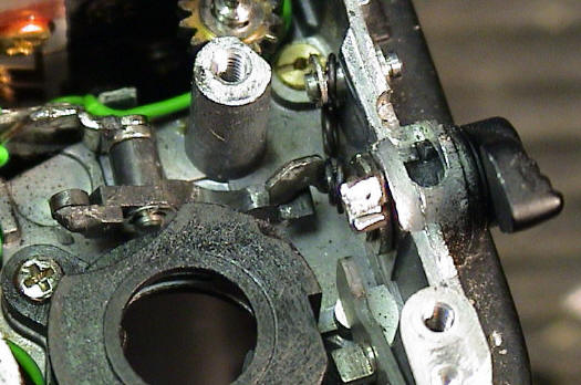
| Here's a
bird's-eye view of the situation. The red arrow points to the offending section - properly mated here. I tweaked (when your repairman says tweaked, he means bent) the metal lever at the green arrow to mate the faces squarely. What actually caused the problem in the first place? The shaft (yellow line) holding the second lever is secured to the plate indicated by the yellow arrow. This plate is not very stable and the entire assembly flexes under pressure. If the levers are not carefully aligned, or if enough repeated pressure is used, the levers will slip past each other. It really needs a redesigned part to permanently fix this issue. |